
It’s just what it says on the tin.

 There is a store called Don Quixote near where I live in Tokyo. Donki (as it’s called by locals) is a singularly unique store. The experience of going to Donki is similar to visiting Fry’s Electronics in Silicon Valley — the first time you walk in there and see oscilloscopes next to Ritz crackers it boggles the mind. But after living there for a few years you come to take if for granted that you can pick up baby diapers, a bare PC motherboard and some soldering flux in a single trip.
When I first moved here and asked people where to buy certain things, a common answer was “Amazon or Donkey” (I didn’t understand the “donki” shorthand yet). Because it’s one of those places where you can literally find just about anything. It’ll be the cheap crappy version of whatever you want, but they’ve got the category covered. Also, they are open 24/7 so if you really really need some clean underwear, contact lenses or a rice cooker at 3AM and don’t mind navigating around the drunk foreigners taking pictures, you can hit up donki.
I went there recently (cat food, socks and file folders) when I came upon a shelf full of digital clocks that claim to set themselves when you plug them in. In a country where there are so many completely useless electronic features on everything, including the toilets, this struck me as a terribly useful and practical improvement on the normal digital clock. And the price for this marvel was 900 Yen which at the time I bought it was about $7.50 USD. I picked one up, plugged it in and sure enough it set itself after a few minutes. Which meant the very next thing I did was tear it apart.
I’ve always liked taking things apart to see how they work. In this case, I knew what I was looking for because the name of the product is “Raiden: Radio Wave Control clock” so it must be using a radio signal of some sort. When I opened it up, the radio antenna was immediately obvious and freakishly huge. In the picture below it’s in the lower left hand corner and consists of a 2 inch ferrite rod wrapped in magnet wire.
In an age where everything has gone digital and tiny, I’m used to seeing those little on-chip antennas or maybe just a long copper-clad trace on a board or a short wire whip antenna. But this thing looked like a prop from an old Frankenstein movie or something. It looked rather out of place next to the tiny clock circuit board and I was intrigued…

I found a good Wikipedia article that explains how the so-called JJY radio signal works. Amazingly the signal covers all of Japan with just two transmitters. It consists of a simple low data-rate signal transmitted at what they call a “long wave” frequency of 40kHz or 60kHz (the two transmission sites operate at different frequencies). These long waves do a much better job going through buildings and walls than the high frequency waves used for things like WiFi or cellular phones, which is why they can get away with just the two transmitters.
To put it in perspective, the human ear can hear frequencies up to 20kHz so these waves are transmitted at frequencies just an octave above that! WiFi operates at 2.5 GHz which means you could fit 50,000 cycles of a WiFi signal in a single wavelength of the Japanese national time signal. Thank you, Google for doing the math.
At this point all I could think was “I want a JJY receiver module for my clock projects and I WANT IT NOW!” But scouring online most of what I found was people desperately trying to purchase them, but they’re kinda scarce and the ones I did find cost around $30 USD. I got a whole damn clock for a quarter of that, so I proceeded to figure out how to scavenge the part from it. The first thing I did was to go back to Donki and buy 4 more clocks because I knew I had a good chance of breaking at least one or two in the process. And of course in the case of success, I’d want more for future projects.
You can clearly see where the two antenna wires attach to the clock’s circuit board.

Flipping the board over to the other side we can see they go to an area of the circuit board with an epoxy-covered module of some sort and a few passive components. Given the weak RF signal it’s trying to pull in, the fact that it’s separated from all the digital stuff made me fairly confident this was the time decoder module.

After some Google searching I discovered that Seiko, the company that makes the clock, also makes the SM9501A Radio Controlled Clock Receiver IC which is probably how they manage to sell that clock so cheaply. But I had no way to verify this, as the IC was encased in epoxy. This also meant I had no idea where the interesting signals were on the board. But I did notice there were a few test pads near the RF circuit. If you were going to test these clocks after manufacturing, the self-setting mechanism would probably be important to test. So with nothing more than this semi-educated guess I wrote a small data-logger program for an Arduino and watched the test pad signals for a few minutes.
There was only a single pad that showed signs of data being transmitted. It was initially high, then after a few seconds it went low and then oscillated wildly for about 30 seconds and then finally got into a rhythm of a single pulse every second. What I was seeing was the RF receiver chip going through a cycle of tuning, AGC and filtering trying to get a clean signal from the transmitter. It was looking like it had stabilized and then it went bonkers again sending what appeared to be total noise. This particular clock ships nationwide in Japan and thus switches between the 40kHz signal that is strongest in South Japan and the 60kHz North Japan signal looking for the strongest and cleanest signal. What I had observed was the clock pulling a signal from one transmitter, then switching to the other. There is a way to tell the chip which to use, but I couldn’t figure out how to access that pin, so I just let the clock do its thing and snooped the signal.
The quality of the signal and the time to acquire a lock varied a LOT based on where in the house the receiver was, time of day, etc. It turns out this is to be expected and the Japanese government ministry in charge of this has data about expected field strength by time of dayon their web site. So far, so good. Now I had to figure out how to decode the signal I was pulling off the circuit board.
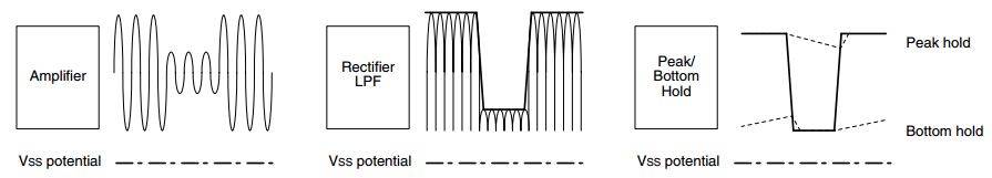
In my attempts to find an off-the-shelf module I read about some American and European versions (it turns out that many countries have such a time signal, although they each have different carrier frequencies and encoding standards) that output the time data as serial protocol data. But the signal I was seeing was super slow and would have effectively been less than 100 baud I believe. So going back to the data sheet for the chip I believed was being used, I saw that the chip doesn’t actually decode the time signal as such. Rather, it handles all the tuning and noise reduction, etc. and then presents the raw signal as digital data. The diagram below from the SM9501A data sheet explains this nicely.

The input is an AM radio signal — 40kHz carrier, with amplitude modulated over time. The chip takes the input wave, which I’m sure bears little resemblance to the beautiful signal shown above, and tries its best to pull a clean digital signal from it. When everything is operating perfectly you receive a single bit of data every second. A bit consists of a low-power pulse of some duration, followed by a full-power signal for the remainder of that given second. This scheme can encode 3 different values: a zero bit, a one bit and a maker bit that is used to frame the data packets. The scheme and the meaning of each of the 60 bits of data is explained well in the Wikipedia entry for the Japan JJY time signal.
Once you have a string of 60 bits, decoding the time is trivial. It turns out the hard part is getting a clean signal. And the method that the SM9501A uses to pass data to the computer is very useful here, because it gives us a lot of insight into what’s going on and even the ability to reconstruct data from a noisy signal.
If the IC hasn’t quite tuned the automatic gain control and filtering, then what you get are spurious transitions between high and low voltage on its output pin. A perfectly clean signal will have exactly one low->high and one high->low transition per second, whereas a noisy signal with spurious transitions will have more than that. My JJY decoder library uses a pin-change interrupt to receive the transitions, and it keeps a count of how many transitions occurred in each of the last 4 seconds. This means with a single number (pulses in the past 4 seconds) we can determine if we have a clean signal or not. Additionally it means that you can see if the signal is trending towards clean (fewer pulses each second) or not.
The chart below shows 60 seconds of signal metrics from a freshly powered-on system. The top graph is of pulses-per-second, where the green range is the perfect 2 pulses per second and yellow and red are increasingly noisier values. I had to clamp the first few values because they were so far above the others — values in the thousands! But as you can see it quickly converged to a good signal after about 15 seconds or so.

The blue portion shows the pulse-width of the AM signal for each second. A long 800ms pulse is a zero bit, a 500ms pulse is a 1 bit and a tiny 200ms pulse is a marker framing bit. If the pulse could be decoded then there is a green bar underneath indicating we received valid data for that second or red otherwise. And finally the actual decoded bit is overlayed on top of the blue pulse for those seconds where we received valid data.
You sync to the signal by finding 2 adjacent marker bits. This indicates the top of the minute, as there is a marker bit at the 59th second and the 0th second of each minute. You can see that this occurred at 33 seconds into the trace above. From there it’s a simple matter of assembling the bits into a number. One odd thing is that the number is encoded in BCD but that’s the only gotcha.
When you are sitting there staring at a serial debug console waiting for the signal to converge and it finally does, it’s very exciting. But then it must remain clean for an entire minute, which all of a sudden feels like an eternity. The full 60 bits of data contains the year, month, day-of-month and some other data as well. But for my simple clock application all I really need is the hours and minutes.
Thankfully getting the hour and minute requires only 20 seconds of clean signal past the start-of-minute marker, which I’m able to get fairly reliably where I live. For best practice, I should wait for the parity bits that come 37 seconds in which would allow me to validate the hours and minutes but so far it seems to be working well. There’s enough things that have to go right to get the first 20 seconds of data that it seems unlikely for one of the bits to be wrong.
Sometimes the stars just don’t align and the signal is only clean for a few seconds here and there. After a while — seems like maybe 10 minutes or so — the receiver chip gives up and shuts down. Presumably because the clock is powered from 2 AA batteries and it’s trying to conserve power. When that happens, there is a button on the clock you can push to ask it to try again. I haven’t worked this logic into my library yet, but I think it’s just a matter of pulling that line low for a second to simulate the button press.

Once I removed the case, speakers, batteries, etc. the size of the board and antenna are small enough to fit into an Arduino-powered clock. The full clock board is around 3in x 1.5in in size. Theoretically I could cut off all the digital side of the board and just use the module, but I don’t know what magic the CPU does to initialize the receiver IC when it comes out of reset etc. so I’m happy making do with the full board for now.
Like anything I’ve ever written, what on the surface seems simple always ends up accumulating some complexity by the time you’re done. The code here is no exception to that. But as is also typical, the bits that look the least “clean” are the parts that make it actually work robustly.
There are 3 stages to the decoder pipeline:
There’s also a bit of logging etc. that can be turned on and off to help see what’s going on during board bring-up. The code uses 3 pins, but you can ignore the LED and BUTTON pins as they are only used for debugging and status purposes. PIN_INPUT is the signal coming from the SM9501A decoder IC:
int PIN_LED       = 9;   // Signal indicator
int PIN_BUTTON    = 8;   // Press to show debug logs
int PIN_INPUT     = 3;   // Data from radio decoder
Want to build your own? Follow these simple steps:
Enjoy!

Lately I’ve been experimenting with how best to print more complicated designs on my Makerbot Replicator. The issues you usually run into are objects with overhangs – areas of plastic that don’t have anything underneath them to support them as they’re being extruded. My typical process has been to design something and then figure out some way to orient the object to minimize overhangs. But lately I’ve discovered some techniques that can easily allow you to print things with minimal support.
As an example, here’s a desk ornament I’m working on for a project. The picture below shows two views of the 3D model as designed. The first rule of thumb I applied here is for continuous surfaces to make sure anything that deviates from vertical creating an overhang does so at an angle of less than 45 degrees. The Android figure is designed at a 30 degree tilt which is sufficient to allow new layers to build upon older ones. Also, the support arms are curved to satisfy this constraint.
")
There are two sections of the design that are not well supported. If you didn’t notice them above, the next picture which shows my first attempt at printing shows the problematic areas well.


As the printer is building up layers, when it gets to the bottom of the body just above the legs it’s literally laying out a string of plastic in the air with nothing to support it. The same thing happens when it reaches the bottom of the arms. What happens is the string usually catches on something in the vicinity and after a few layers can end up providing just enough support for the layers above it. You can see that in the pictures above – there are about 10 layers of string but beyond that things worked fairly well.
This made me think that perhaps adding just a little bit of support structure to hold those first layers (and that could be cut off later) would solve the issue. But looking at the arm, the very first layer is a tiny little little corner and might not be enough to build on. So first I sliced the bottom of the arm parallel to the ground by about 1/10th of an inch to expose some surface. The first picture shows the side view of the sliced arm and the second shows a view looking up at the arm from the ground. The blue selected outline is the first layer of plastic we’ll need to support.


So I designed some small rods and positioned them at the corners and apex of the blue profile curve so there would be something for them to attach to. Supporting the perimeter is usually enough, as the infill is made by zig-zagging back and forth which ends up sticking to the perimeter.
 It turns out it was the correct strategy, but I failed several times in how I connected the support to the build platform. My theory was to make the supports tiny little pins so they would be easily broken off. But my first try the pins were so tiny they got knocked down or apart and didn’t last long enough to support the arm. The picture here shows the tiny pin supports on the right failing to support the arm layers. And the pins I had put on the left got knocked over during the print.

The second try is shown here. I made the supports small rods of 0.075 inches in diameter. This was enough to support the layers but also small enough to break off by hand. However, the bottom of the support base wasn’t large enough and didn’t stick reliably to the build platform. When printing with ABS anything with much mass needs a decent surface area to stick to the platform.
In my final attempt I made large ovals for the support bases and started the print. Three hours later the result was great. Below is a sequence of photos showing the result in the printer, then some details of the support structure. The final picture is after I snapped them off by hand, which required very little force.


The final result after some light cleaning with a knife and sanding down some areas is shown below. It’s encouraging enough that I can see doing some more ambitious parts that I previously had thought were not printable with a Makerbot.


I published the 3D design files at Thingiverse so you can print your own. http://www.thingiverse.com/thing:32836